How to wire a pass-through switch to control lights from 3 locations
Often there is a need to control lighting from several points dispersed in space. In many cases, several remote controls placed in different places can help. But this method is not always applicable, and has its own disadvantages. For example, in the form of the need for periodic replacement of batteries, which run down at the most inopportune moment. Therefore, the classic solution with wall switches has a firm preference.
Examples of light control from three points
Such a scheme can be useful in T-shaped passageways and corridors. The light can be turned on at any point when entering, and turned off when exiting, regardless of the direction of travel. This system can also be useful in bedrooms or in children's rooms for two people. A switch at the door turns the light on, and at each bed it goes off. Or vice versa - when you get out of bed, you can turn the light on, and when you leave the room, turn it off.
If there is a staircase consisting of two spans, a similar principle can also be implemented on it. Lights can be switched on and off from below, above and between bays. There can also be other situations where such a scheme can be useful - it is impossible to predict all cases.
Switching devices used
To create a lighting switch circuit with 3 places, you need to use three light switches, externally similar to the usual ones. The differences are inside.
Devices of through-type
To build a given lighting system will need a pass-through single-key switch. It looks the same as the standard, but often has a marking in the form of a schematic designation of the stairwell or arrows, although not always. Not all manufacturers, including world leaders in electrical engineering, take the trouble to apply additional icons. Because international standards do not require it.
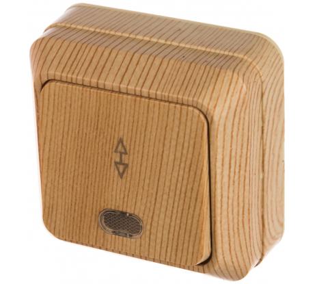
The fundamental differences are inside the apparatus. They can be seen immediately - instead of the usual two terminals, the feed-through unit has three.
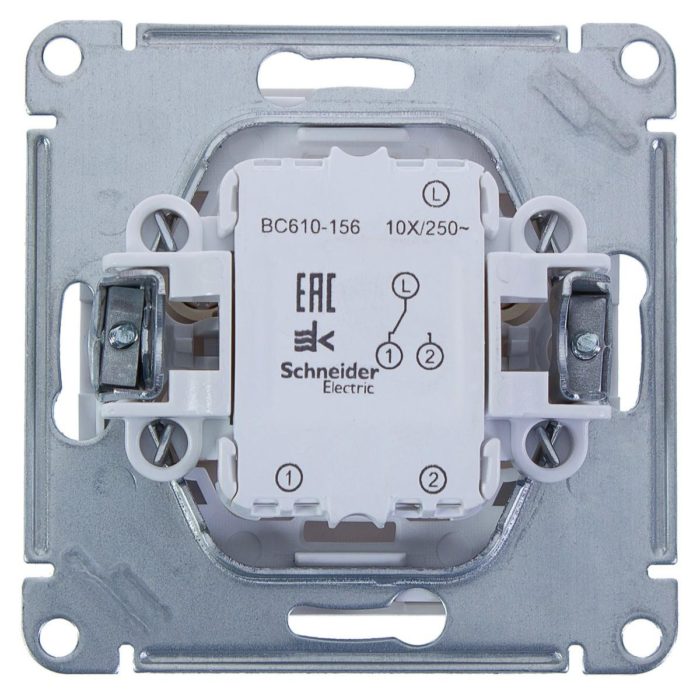
This is caused by a difference in the device of the contact group of such a switching device. Instead of two contacts for closing/opening, it has a toggle group for switching. In one position one circuit is closed, the other is open. In the other, it is the other way around.
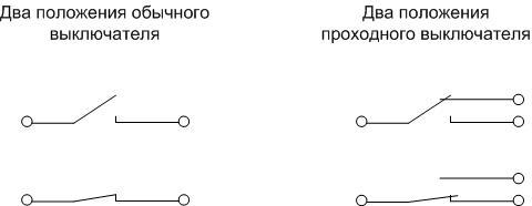
Devices of the pass-through type also come in two- and three-key versions. In this case, they control two and three groups of contacts to switch. This property of such switching elements is used to build schemes of independent control of light from different points. Using two such devices, you can turn on and off the lights from two places.
Cross-type device
To build a three-point independent control circuit, you need another type of switch - a cross-over switch (sometimes called a reversing switch). It is not labeled, so from the front it is indistinguishable from a normal switch.
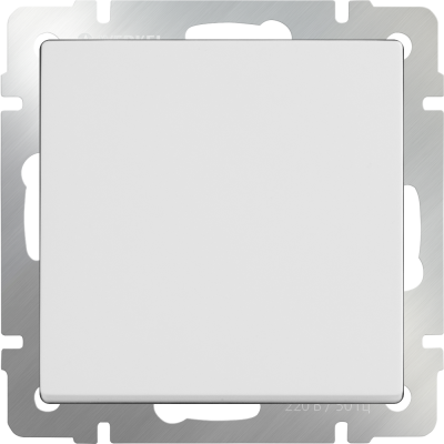
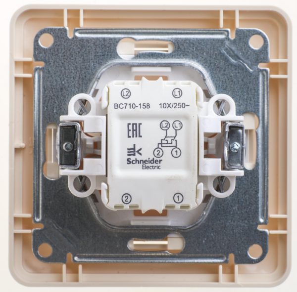
Similar to the previous case, all the differences are inside the unit and are visually noticeable from the back side - such a device has four terminals and two contact changeover groups.
The circuit diagram of any cross-over switch is assembled as follows:
- the changeover contacts are free and led to separate terminals;
- the normally open contact of one group is connected to the normally closed contact of the other group, the point of connection being brought out to the terminal;
- the normally closed contact of one group is connected to the normally open contact of the other group, the connection point is led out to the terminal.
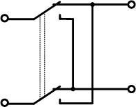
If you analyze the operation of such a switch, the origin of the term "reversible" becomes clear - it can be used to reverse the polarity of the DC voltage, which reverses, for example, the direction of rotation of a DC motor. To build a lighting system with three-point control, you would need one such device.
Just like conventional devices, feed-through and crossover switches come in overhead and indoor versions. The former are mounted on the plane, the latter - in a specially designed recess in the wall.
Scheme of light control from three places
With the help of two loop-through elements and one cross-over element, you can build a scheme for turning on and off lights from three locations spaced apart.
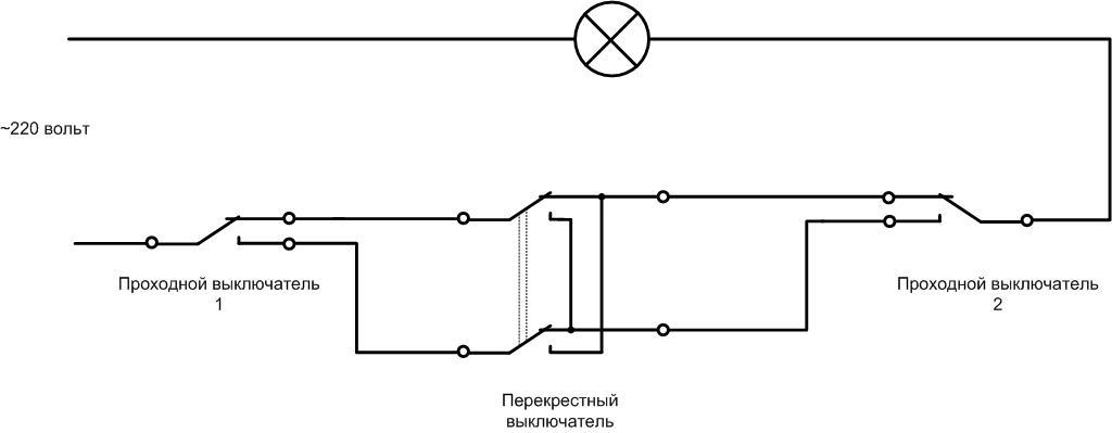
All the apparatuses are connected in series in the phase gap of the lamp power circuit. Obviously, each switch individually can build a circuit or disconnect voltage by reversing the state, regardless of the position of the other switching elements.
Materials and tools for setting up a control circuit
First of all, it is necessary to determine the topology of laying cables and lighting wires. Since all switches are connected in in series, it makes sense to lay the conductors daisy chain without the use of junction boxes. This method is suitable for both concealed and exposed wiring.

You will need a cable with a cross section of 1.5 mm²:
- two-core cable from the switchboard to the first through-break switch;
- three-core cable from the first through-breaker to the crossover;
- three-core cable from the crossover to the second through switch;
- two wires from the second crossing to the luminaire (group of luminaires).
In this version, the neutral wire goes together with the phase wire along the entire length of the wiring. The disadvantage of this solution is the need to connect the neutral conductor at several points, which is undesirable for safety reasons - the probability of zero breakage due to the many terminals or stranding increases. You can run this line as a separate wire directly from the switchboard to the lamp, then the number of wires in each section will be reduced by one.
If you can't do without a distribution box or if the control circuit is to be installed in an existing lighting system, the wiring can be done in a different way.
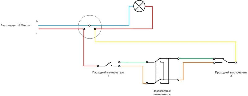
Galvanically, this scheme does not differ from the previous one and works in the same way. Connection of the first and last switch is made in the gap of the phase wire in the box.
| Cable | Material of conductors | Number of conductors | Additional features |
| VVG 1x1.5 | copper | 1 | |
| VVGng 2 x 1,5 | copper | 2 | Non-combustible |
| VVG 2 x 1.5 | copper | 2 | |
| NYY-J 3x1,5 | copper | 3 | |
| VVG 3x1.5 | copper | 3 |
The names of some cables suitable for use in the arrangement of the circuit are given in the table.
Installing switches
If the type of wiring is selected, cables with the right number of strands are laid and are equipped with subcrockets when concealed wiring, mounted overlays when open, you can proceed directly to circuit breaker installation. To do this you will need tools:
- wire cutters to shorten the conductors;
- An arborist's knife or an insulation stripper to strip the ends of the conductors;
- a screwdriver set for tightening the terminals, screwing in the fastening hardware, and tightening the release tabs.
You may also need other small tools.
Important! Any installation should begin with disconnecting the voltage in the switchboard and checking the absence of voltage directly at the place of work (multimeter, screwdriver-indicator or low voltage indicator).
The first pass-through device can be installed on the first floor of the house near the front door, the second on the second floor near the stairwell, the third on the third floor also near the stairs. Then it is possible to turn the light on when you enter the house and turn it off when you go up to the desired floor. In addition to the switches, such a scheme will require a cable for the wiring that connects the switches.
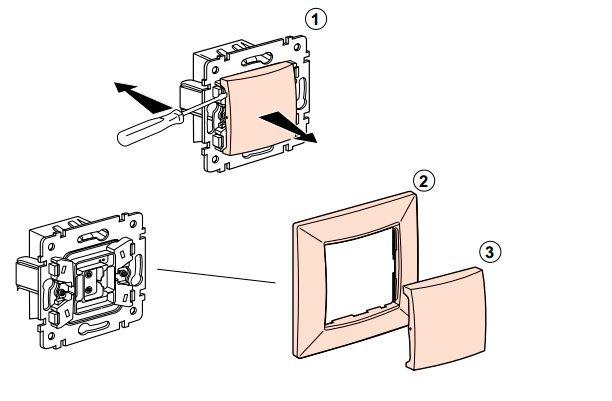
First you have to partially disassemble the switch - remove the key and the decorative frame.
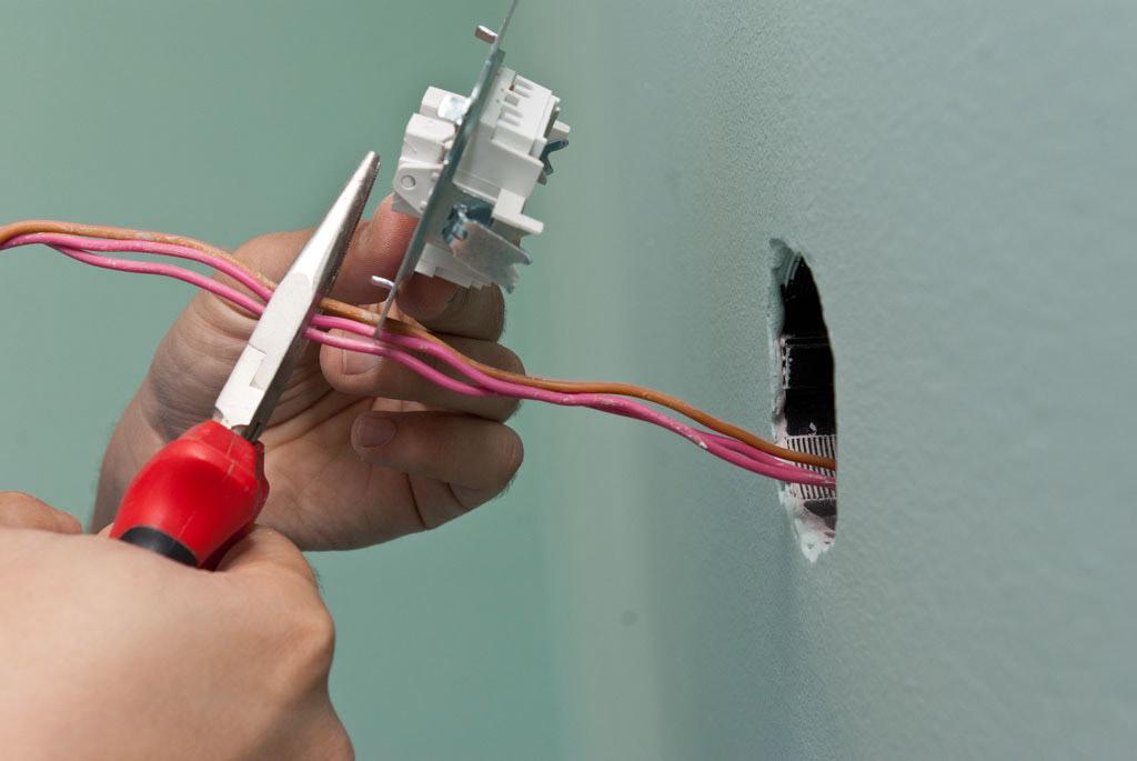
Next, you need to shorten the wires sticking out of the wall, to a reasonable length - so that when you install the switch, they are completely tucked into the recess.
The shortened wires should be stripped by 1-1.5 cm, inserted into the terminals of the electrical appliance and securely clamped.
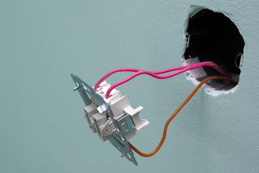
Then the appliance must be carefully installed in its intended place and fastened according to its design.
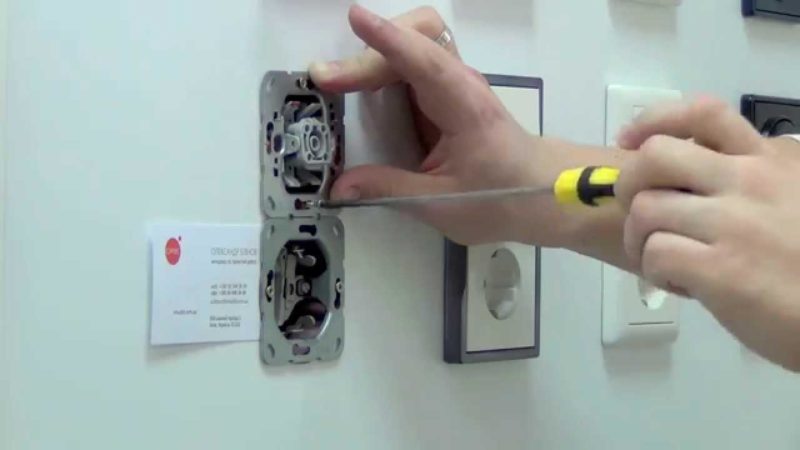
Some types of devices require fixing the metal frame with self-tapping screws, some require unfastening the petals. There are devices that have both types of fixation combined. After that you can put on the decorative frame, install the key and move on to the next appliance. The cross switching element is mounted in the same way as the 3-point through switch, but it has four conductors to it - two on each side.
After the installation work is complete, you can apply voltage to the control circuit and try it out.
Video lesson: Wiring a loop and crossover switch, designed to control lighting from three or more points.
Possible errors
With a careful approach to installation, the likelihood of mistakes is small. But it is still possible to mix up the type of switches when buying. It is necessary to carefully read the technical specification for the devices and pay attention to the back - there is often a wiring diagram.
In order to minimize installation errors, it is advisable to sketch the wiring diagram of the feed-through and crossover switch from 3 places and mark the terminals of the devices before starting the work. If colored or numbered cables are used (and this will make the job much easier), the colors or numbering should also be sketched. If the cores do not have factory markings, you will have to call each conductor and mark it (in the form of several stripes or dots with a marker, fixing a tag with an inscription, etc.). It is also a good idea to label each circuit installed and tested in the schematic.
It is not difficult to make and connect a system of independent light control from three points. It is only necessary to carefully study the material part, its principle of operation and to nullify the possibility of mistakes in the installation before the first turn on.
