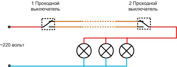
How to connect a light bulb to two switches
In some cases, there is a need to fully control lighting from two points. This may be necessary in production in long aisles or in warehouses with several exits. A person who enters through one entrance can exit through the other and turn off the light behind him. In everyday life, such a need may arise in the bedroom - it is convenient to turn on the light at the entrance, and turn it off next to the bed. Creating such circuits is possible, but there are some features that are offered for review.
Pros and cons of control from multiple points
The main advantage of the decision to connect 2 switches to 1 light bulb is to increase the level of comfort. Such a scheme allows you not to waste time on returning to the place of installation of the switching device to deactivate the lighting. Also, the use of such a principle of control allows you to save energy by reducing the operating time of the lighting elements.
There are few disadvantages to such a system, but the main one is It is impossible to tell by the position of a single switch whether the lights are energized. The disadvantages also include the need to make additional technical decisions when it is necessary to prioritize the control of light from the central panel.
Which switches to use
With conventional (key) switching elements, which operate on short-circuit and open-circuit, different schemes for connecting two switches per lamp can be implemented.
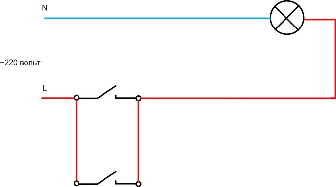

The conclusion is unambiguous - with the help of simple switches you can not organize a full-fledged scheme of independent control from two places.
Loop switch
In this case it is necessary to use loop-through (marching) light switches. They do not differ externally from the standard ones in most cases, but they have a specific contact group.
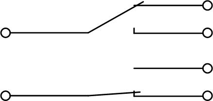
While the key device opens an electrical circuit in one position and closes it in another, the marshalling device works differently. In one position it closes one circuit (the other is open), in the second position it closes, on the contrary, the second circuit (the first is open). Therefore, such devices are often called switches.
Marching devices come in one- and two-key versions. The latter are distinguished by the presence of two contact groups, which are independently controlled by two keys.
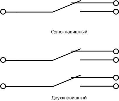
Sometimes the front side of the walk-through device is marked in the form of a flight of stairs or two arrows.
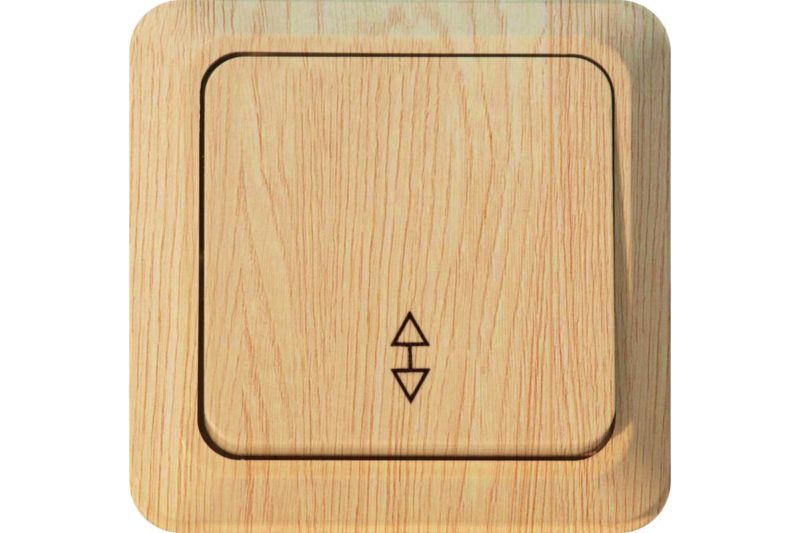
But there are no unified requirements for the marking on the front panel of switching devices. Many manufacturers, both the world's top names in the electrical industry and little-known companies, often neglect such markings. Therefore, you can determine the purpose of the appliance in other ways:
- by asking the seller;
- By studying the switch's data sheet;
- by the marks on the back.
On the back there is usually a diagram of the contact group and the connection of each element to the terminals.
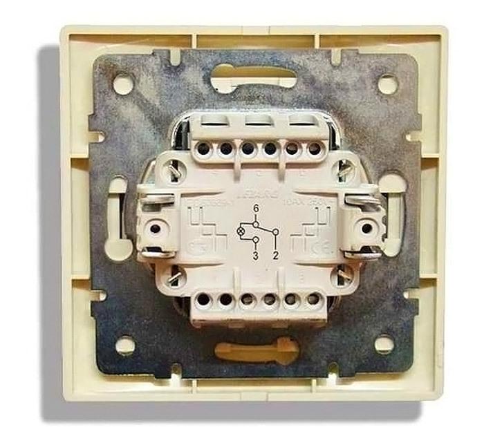
Some manufacturers label the terminals with alphabetic symbols instead of a diagram. For example, a toggle contact with the letter Land the stationary elements with N1 и N2. There is also no common standard here, so the letters may vary.
Wiring diagram of the two devices
The marshalling switch can be used as a regular switching device, but it is not rational - it costs more than a standard key. Devices with a toggle group are specially produced for the organization of lighting circuits, independently controlled from two or more points.

This scheme is going to be assembled from two in series marshalling devices connected in series. Obviously, no matter what position one of the switches is in, the second can always close or open the circuit of the luminaire power.
If you need a control circuit of three or more places, it is necessary to use cross apparatuses together with the marching switches. It is not possible to build such a system on pass-throughs alone. But if there are two two-way two-key devices, you can organize independent switching of two light sources from two different locations.
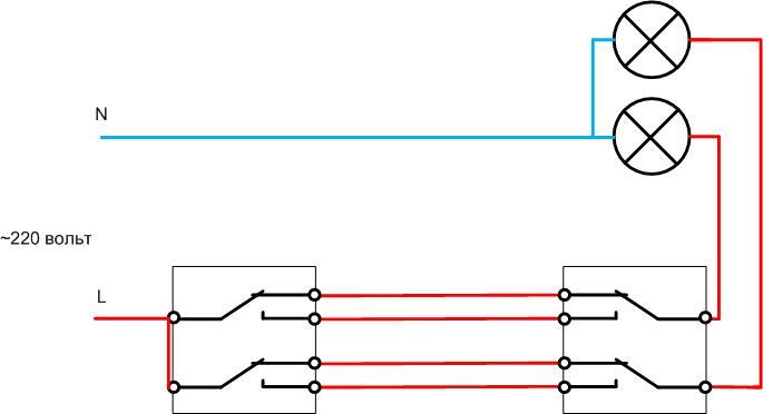
Such a scheme is useful, for example, where there are two lighting systems in the same room - general and local. So you can set two levels of brightness in steps.
Safety conditions
The main condition for the safe operation of the lighting system is that all of its elements must be in good working order. During the work it is necessary to monitor this and replace faulty elements in time (also respecting the rules of health and safety).
Installation of lighting circuit elements must be carried out so that the current-carrying parts are not accessible to intentional or accidental contact. All connections in distribution boxes must be insulated after completion of work and before the first application of voltage. Switching elements used must have a margin of at least 20% for the full load current.
| Through-type switch | Number of contact groups | The greatest current load, A |
|---|---|---|
| UNIVersal Allegro IP-54, ser. 1276 | 1 | 10 |
| Jilion 9533456 | 1 | 10 |
| Lezard DEMET with backlight, cream 711-0300-114 | 1 | 10 |
| Panasonic Arkedia white 54777 WMTC0011-2WH-RES | 1 | 10 |
| Livolo VL-C701SR-14 Touchscreen | 1 | 5 |
Obviously, it makes no sense to look for a device rated for more than 10 amps - such a load will be turned off by a line protection circuit breaker.
If the circuit will be operated in a TN-S or TN-C-S network (with the presence of a protective earth conductor PE), this conductor must be installed upstream of each luminaire. If there is nowhere to connect it at the time of installation (e.g. if incandescent bulbs are used), it will still be useful in the future when replacing lighting fixtures with newer ones. If luminaires with protection class 1 are used, grounding is the only way to ensure safety at work. For these devices, the PE conductor must always be connected to the terminal marked with the ground symbol (or the letters PE). Without grounding, such chandeliers cannot be operated.
Video: A simple way to connect 2 switches in one lamp.
The circuit should be connected to a separate circuit breaker in the switchboard. Many years of experience has shown that the lighting network carried copper wire with a cross section of 1.5 sq.mm. A larger cross section is unjustified economically, a smaller may not pass on the load current and mechanical strength. To protect such a line must be installed circuit breaker for a current of 10 A. If you use a circuit breaker with a higher current, its sensitivity may not be enough, which will lead to overheating of the wires and melting of the insulation. The use of circuit breakers with a lower current must be confirmed by calculation - it should not falsely operate at the rated load with a margin of 20-30%. In many cases, 6-amp circuit breakers can be used, especially when building a lighting network on LED lights.
Also will be helpful: 4 steps for installing a wall switch
Connecting two switches to one light bulb should not cause insurmountable difficulties for a craftsman with at least a basic knowledge of electrical engineering. The materials of this review will help in case of doubt.
