RGB LED Specifications
Backlight, changing its color, looks spectacular. It is used for advertising objects, decorative lighting of architectural objects, during the various shows and public events. One way of implementing such illumination - the use of three-color LEDs.
What is an RGB-LED
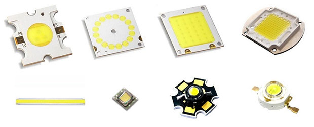
Conventional light-emitting semiconductor devices have a single p-n junction in one package, or a matrix of multiple identical junctions (COB technology). This allows one color of luminescence at any given time, either directly from recombination of the basic carriers or from secondary luminescence of the phosphor. The second technology has given developers a wide range of options in the choice of colors of glow, but to change the color of radiation during operation of the device can not.
RGB LED contains three p-n junction in one body with different colors of luminescence:
- Red;
- green (Green);
- Blue.
The abbreviation of the English names of each color and gave the name of this type of LED.
Types of RGB LEDs
Tricolor LEDs by the way the crystals are connected inside the body are divided into three types:
- with a common anode (have 4 pins);
- With a common cathode (have 4 pins);
- with separate elements (have 6 pins).
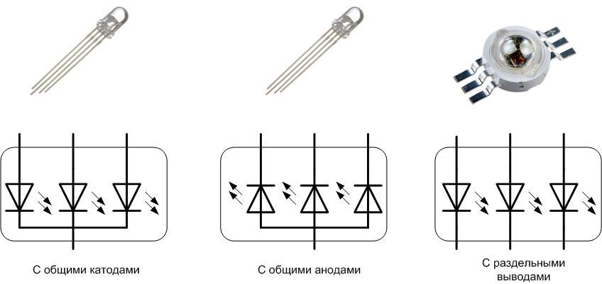
Depends on the design of the LED depends on how the device is controlled.
According to the type of lens LEDs are:
- With a transparent lens;
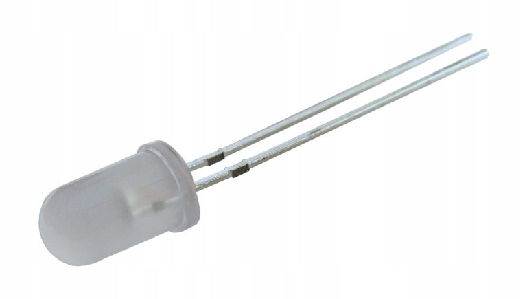
- With a frosted lens.
For RGB elements with a transparent lens for mixed colors may need additional light diffusers. Otherwise, individual color components may be visible.
Working Principle
The principle of operation of RGB LEDs is based on the mixing of colors. Controlled ignition of one, two or three elements allows for different glow.
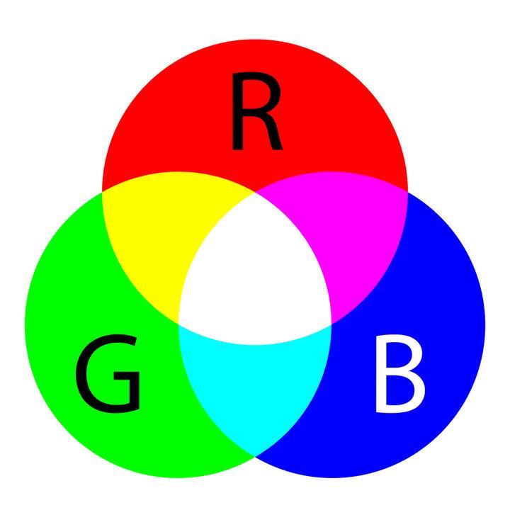
Turning the crystals on individually gives three corresponding colors. Pairwise inclusion allows a glow to be achieved:
- red+green p-n junctions will eventually give a yellow color;
- Blue+green will give turquoise;
- red+blue gives you purple.
The inclusion of all three elements produces white.
Much more possibilities are given by mixing colors in different proportions. This can be done by separately controlling the brightness of each crystal. To do this, it is necessary to adjust the current flowing through the LEDs individually.

RGB-LED control and circuit design
Controlled RGB-LEDs the same way as conventional LED - by applying a direct voltage to the anode-cathode and the creation of current through the p-n junction. Therefore, it is necessary to connect the tricolor element to the power supply through ballast resistors - each crystal through its own resistor. To calculate it can be calculated through the rated current of the element and the operating voltage.
Even when combined in the same enclosure, different crystals may have different parameters, so they cannot be connected in parallel.
Typical characteristics for a low-power tricolor device with a 5 mm diameter are shown in the table.
| Red (R) | Green (G) | Blue (B) | |
| Maximum direct voltage, V | 1,9 | 3,8 | 3,8 |
| Rated current, mA | 20 | 20 | 20 |
It is obvious that the red crystal has a direct voltage twice as low as the other two. Connecting the elements in parallel will cause different brightness or failure of one or all p-n junctions.
Constant connection to a power supply does not allow to use all possibilities of the RGB cell. In static mode, a tricolor device only performs the functions of a monochrome device, but costs much more than a regular LED. Therefore, much more interesting is dynamic mode, in which you can control the color of the glow. This is implemented by means of a microcontroller. Its outputs in most cases provide an output current of 20 mA, but this has to be checked in the datasheet each time. It is necessary to connect the LED to the output ports with a current limiting resistor. A compromise variant is 220 ohms resistance if the chip is powered from 5V.

Elements with common cathodes are controlled by feeding logic 1 to the output, with common anodes - logic zero. It is easy to change the polarity of the control signal via software. LEDs with separate outputs can be connect and control in any way you want.
If the microcontroller outputs are not designed for the rated current of the LED, you have to connect the LED through transistor switches.
In these schemes both types of LEDs are lit by applying a positive level to the inputs of the switches.
It was mentioned that the brightness is controlled by changing the current through the light-emitting element. The digital pins of the microcontroller cannot directly control the current because they have two states - high (corresponding to the supply voltage) and low (corresponding to zero voltage). There are no intermediate positions, so other ways are used to regulate the current. For example, the method of pulse width modulation (PWM) of the control signal. Its essence is that the LED is not supplied with a constant voltage, but with pulses of a certain frequency. The microcontroller according to the program changes the ratio of pulse to pause. This changes the average voltage and the average current through the LED while the voltage amplitude remains unchanged.

There are specialized controllers designed specifically to control the glow of tricolor LEDs. They are sold as a ready-made device. They also use the PWM method.

Pinout
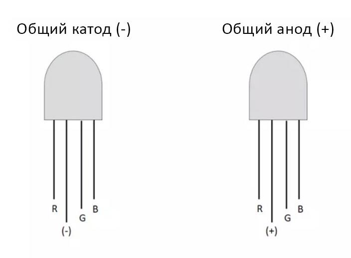
If there is a new, unsoldered LED, the pin assignment can be determined visually. For either type of connection (common anode or common cathode), the lead connected to all three elements has the longest length. If you turn the case so that the longest leg is on the left side, the "red" lead will be on the left, and the "green" lead will be on the right side first, then the "blue" lead. If the LED was already in use, its pins may have been shortened arbitrarily, and you will have to resort to other methods to determine the pinout:
- You can determine the common wire with a a multimeter. It is necessary to switch on the device in the diode test mode and connect the terminals of the device to the assumed common leg and to any other leg, then reverse the polarity of the connection (as in the usual semiconductor junction test). If the assumed common lead is defined correctly, then (with all three elements in good condition) the tester will show infinite resistance in one direction, in the other - finite resistance (the exact value depends on the type of LED). If in both cases the tester display will show a breakage signal, it means that the pin is selected incorrectly and you must repeat the test with the other leg. It may happen, that the test voltage of the multimeter is enough to ignite the crystal. In this case you can additionally check if the pin assignment is correct by the p-n junction glow color.
- Another way is to apply power to the assumed common pin and any other leg of the LED. If the common point is selected correctly, you can verify this by looking at the glow of the crystal.
Important! When testing with a power supply you must smoothly raise the voltage from zero and not exceed the value of 3.5-4 V. If there is no regulated source, you can connect the LED to the DC voltage output via a current limiting resistor.
With LEDs with separate pins the pin assignment comes down to clarification of polarity and the arrangement of the crystals by color. This can also be done by the methods listed above.
It will be useful to read:
Pros and cons of RGB LEDs
RGB-LEDs have all the advantages of semiconductor light-emitting elements. This low cost, high energy efficiency, long life, etc. A distinctive advantage of tricolor LEDs is the ability to produce almost any shade of glow in a simple way and at a low cost, and color change in the dynamics.
The main disadvantage of RGB LEDs is the inability to obtain pure white color by mixing the three colors. This would require seven shades (as an example, the rainbow - its seven colors are the result of the reverse process: the decomposition of visible light into its components). This imposes restrictions on the use of three-color luminaires as lighting elements. To somewhat compensate for this unpleasant feature, the RGBW principle is used in the creation of LED strips. For each tri-color LED is installed one element of white glow (due to phosphor). But the cost of such a lighting device increases markedly. There are also LEDs of RGBW version. They have four crystals installed in the body - three for the original colors, the fourth - to produce white light, it emits light from the phosphor.

Service life
The lifetime of the device of three crystals is determined by the MTBF of the shortest element. In this case it is approximately the same for all three p-n junctions. Manufacturers declare the service life of RGB elements at 25,000-30,000 hours. But this figure should be treated with caution. The stated lifetime is equivalent to 3 to 4 years of continuous operation. Hardly any manufacturer has conducted life testing (and even in different thermal and electrical modes) for such a long period. During this time, new technologies appear, tests have to be started all over again - and so on to infinity. The warranty period of operation is much more informative. It is 10,000-15,000 hours. Anything beyond that is mathematical modeling at best, and naked marketing at worst. The problem is that the common inexpensive LEDs usually have no information about the manufacturer's warranty. But you can aim for 10,000-15,000 hours and keep about the same amount in mind. And beyond that, you can only rely on luck. And one more point - the service life depends very much on the thermal mode during operation. Therefore, the same element in different conditions will last a different amount of time. To extend LED life time it is necessary to pay attention to heat dissipation, not to neglect radiators and create conditions for natural air circulation, and in some cases to resort to forced ventilation.
But even the reduced time is a few years of operation (because LEDs will not work without pauses). Therefore, the emergence of tricolor LEDs allows designers to widely apply the semiconductor devices in their ideas, and engineers - these ideas to implement "in iron".
