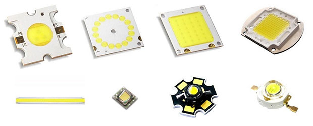
Features and appearance of SMD LEDs
The desire for miniaturization of electronic devices has led to the creation of lead-free radio elements. This tendency didn't skip LEDs - SMD-devices were quite popular in many areas and almost squeezed them out of the market.
What is an SMD LED
The SMD LED is a Surface Mounted Device. Whereas conventional true hole SMDs require a hole to be drilled and soldered to the board for mounting, the SMD LED is a surface mounted device. solder The SMD pins are soldered directly to the tracks located on the upper plane of the printed circuit board.
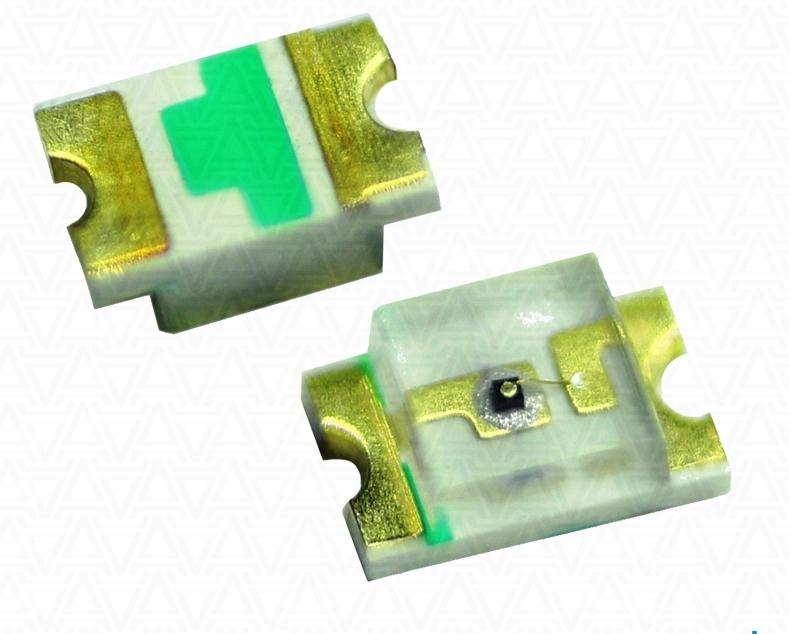
In principle, the SMD element is built the same way as its SMD prototype. On a ceramic substrate is fixed p-n junction of semiconductor, which has a pronounced glow effect when a direct voltage is applied. It is covered on top by a lens of transparent compound. If necessary, a layer of phosphor is applied on top. The main difference is that there are no flexible leads. Contact pads are provided for soldering directly to PCB polygons.
Advantages and disadvantages of SMD LEDs
On the whole, the pluses outweigh - As a result, finished products have smaller dimensions, less weight and lower cost.
There is a myth about unrepairability of electronic equipment, made with SMD-elements. But it is only a myth. Functionability of such equipment can be restored, it requires a little extra equipment, as well as increased experience and qualification of the master.
Types and types of SMD
Conventionally, almost all LEDs are divided into two global categories:
- intended for lighting;
- Designed to indicate the state of electronic devices.
For the first category SMD elements have almost completely displaced the pins, in the second - leaving them a narrow niche. Therefore, the same classification can be applied to surface mount emitting elements.
The dividing line runs along technical specifications:
- for lighting elements, luminous flux is important and requires a color that is close to natural;
- indicator elements are not so much about color and brightness, but rather about contrast to the surrounding background.
Therefore, you can use LEDs with p-n junction luminescence for indication and only with phosphor coating for lighting. Although it is also quite conditional - no one forbids the use of devices with phosphor and white glow for indication.
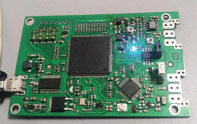
All of this refers to LED optical, visible range. As a separate type of LED SMD should mention devices with a spectrum of radiation lying beyond the perception of the human eye. These include ultraviolet and infrared emitters. The first are used to create compact sources of UV radiation. They are used for currency detectors, search for biological traces, etc. The latter are used in signal transmission systems - in remote controls of household appliances, in security alarm systems, etc. These LEDs are also available in SMD format.
We should also mention LED matrices for lighting systems, produced by the most advanced COB technology to date. Contrary to popular belief, this production principle does not contradict the SMD format. И COB-LEDs . LEDs are produced, including Surface Mounted Device.
Dimensions SMD-LEDs
The type of LED is denoted by the dimensions of its body. Thus, the common size LED 5050 means that the light-emitting element is placed in a shell length and width of 5.0 mm.
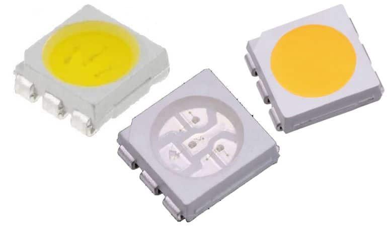
Important! The marking only indicates the housing size. Electrical and optical characteristics of LEDs even of the same size can vary depending on the type and number of installed crystals, so to uniquely determine the parameters it is necessary to use the technical specifications for LEDs.
Correspondence of the sizes of common SMD LEDs in the table:
| Size | Assembly length, mm | Assembly width, mm | No. of radiating p-n junctions | Luminous flux, lm | Rated current, mA |
| 3528 | 3.5 | 2.8 | 1/3 | 0.6..50 | 20 |
| 5050 | 5.0 | 5.0 | 3/ 4 | 2..14 | 60/80 |
| 5630 | 5.6 | 3.0 | 1 | 57 | 150 |
| 7020 | 7.0 | 2.0 | 1 | 45..60 | 150 |
| 3020 | 3.0 | 2.0 | 1 | 8..10 | 20 |
| 2835 | 2.8 | 3.5 | 1 | 20/50/100 | 60/150/300 |
Dimensions of LEDs for indication purposes are marked according to the international standard EIA-96 in inches. The most common housings are 0603 and 1206.
| Designation of size | Size in inches | Metric Dimensions, in mm | Metric Conformity |
| 0603 | 0.063''x 0.031'' | 1.6 x 0.8 | 1608 |
| 1206 | 0.126''x 0.063'' | 3.2 x 1.6 | 3216 |
The same rule applies here - LEDs of different colors of glow, different operating currents, etc. can be made in housings of the same size. Therefore, it is not possible to fully determine the parameters by the EIA designation.
SMD marking
The SMD format was born out of a desire to miniaturize electronic components, so there is no place to put type and specification information on them. Even if you set your mind to it, the markings will be too small to be read comfortably. Therefore, the marking is reduced to the marking of the device terminals. This is important because although LEDs belong to the class of diodes, they are of little use for reverse current locking due to their low tolerance to reverse voltage. If a conventional diode is installed without observing polarity, this manufacturing defect is easy to detect and correct. The light emitter, on the other hand, is very likely to fail after powering up. Even if the problem is detected before the voltage is applied, the miniature indicator LED is problematic to dismantle with a soldering iron - it is easy to melt the transparent plastic cover covering the p-n junction.
Therefore, when installing indicator LEDs, you need to pay attention to the mnemonic pattern indicating anode or cathode location.
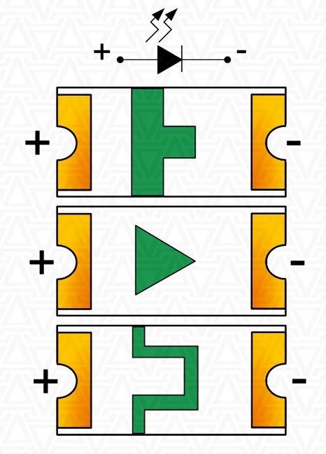
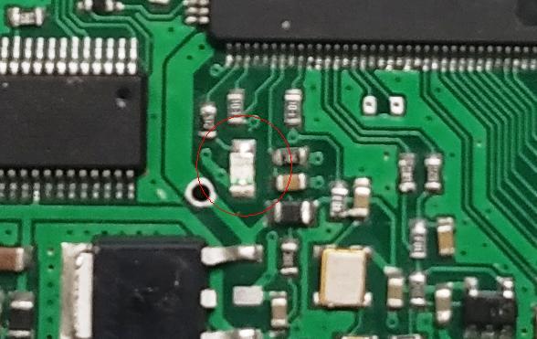
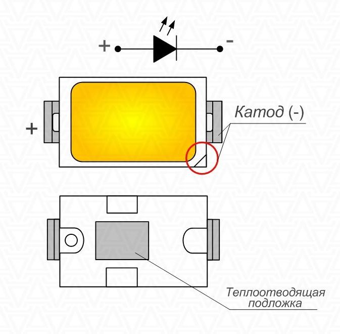
Elements designed for lighting, usually have a bevel, flush or notch on the housing - in most cases, it means cathode. But there is no guarantee that the manufacturer strictly follows this rule. Therefore, in case of doubt, it is better to be on the safe side and check LED (at least one of the batch) with a multimeter.
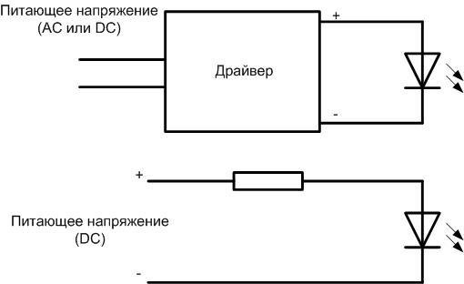
It was mentioned that the SMD element is not different from a normal LED, except for the leadless housing. Therefore, the connection scheme will also be the same. Supply voltage to the LED should be through a driver or a limiting resistor, observing the polarity.
LEDs can be connected in series chains, which are then connected in parallel to form matrices. This combination achieves the required power at a given supply voltage.

When repairing lighting fixtures with replacement of radiating elements (one or more) during operation, the board should be protected from bending and mechanical stress. All SMD elements in such conditions are prone to the formation of microcracks in the housing, breaking the integrity of the soldering, invisible to the eye. As a result of such repair you can get several faulty LEDs instead of one and loss of time for troubleshooting. It is better not to remove the board at all, but it is mounted on a heat sink, which has a large mass and heat capacity, so you will need a soldering iron or a high-power hair dryer to heat the solder. If you are sure that a particular LED has failed, you can try not to unsolder it, but to bite it out. But care must be taken not to mechanically damage the printed wires. When reinstalling a serviceable element, you must remember that LEDs are sensitive to overheating and try to avoid prolonged soldering.
Topical video:
When designing homemade lighting devices, you should keep in mind the problem of heat dissipation from LEDs. The board must always be mounted on an additional heat sink of sufficient area, and for this it must have an appropriate design (no elements on the back side, screw holes for mounting, etc.).
Despite some disadvantages, the SMD format of electronic components has caught on in the radio electronics industry. The contribution of miniaturized pinless elements to the cheapening of electronic devices in the last decade is very weighty. LEDs are also part of this process.
